Can Expander
Ever wonder what would happen if you dumped a multi megawatt
electrical pulse through a solenoid inside of an aluminum beverage can?
No? Then prepare your mind for expansion.
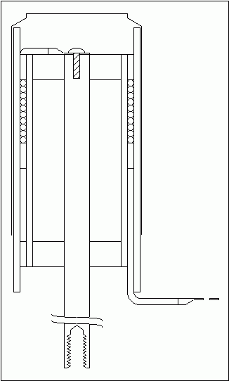
This drawing shows the expander coil. Ten turns of 14
gauge magnet wire, with crimp on, 3/8", ring terminals, are wound around
a 5" length of 2" OD X 1.75" ID polycarbonate tubing and held in place
with two split rings made from 2.25" OD X 2" ID polycarbonate tubing.
The coil is covered with a 6" length of 2.5" OD X 2.25" ID polycarbonate
tubing, held in place by a friction fit, which insulates the can from the
coil. The tube holding the coil is centered around a 15" length of
1/2" OD copper rod with two 1/2" thick polycarbonate rings 1.75" OD X 1/2"
ID. The upper ring is epoxied to the tube, the lower ring is not
and both are friction fit over the copper rod. The copper rod is
drilled and tapped to accept a 1/4"-20 machine screw at the top end and
the 3/8"-16 terminal of my pulse capacitors at the bottom end. A
third split ring near the bottom of the inner tube, helps hold the wire
in place.
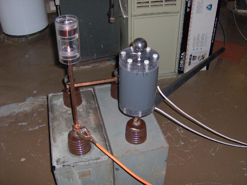
The above photo shows the can expander coil attached to my pulse capacitors
and triggered spark gap, with ground, charging, trigger and measure connections
in place. (The rest of the set up is the same as before.)
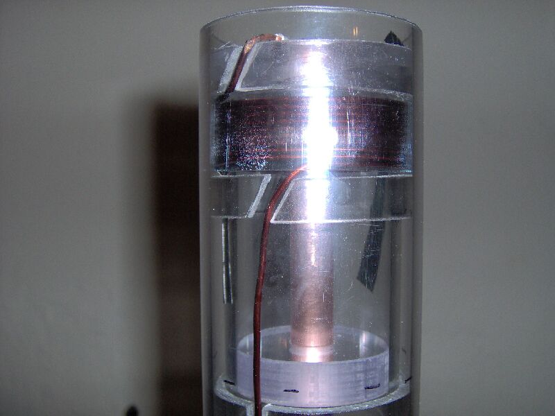
Here is a close up of the expander coil.
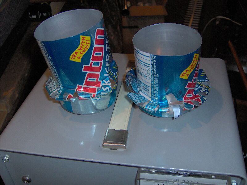
And here are a couple of cans, expanded at 30 and 35 KV, respectively.
Higher power just rips the can apart. The coil has a measured inductance
of 6.5 microHenrys and the capacitor bank has a measured capacitance of
1.488 microFarads. This implies a discharge time (one quarter cycle
of the oscillation frequency, which is = 1/(2*pi*sqrt(LC))) of 4.9 microseconds.
Stored energy (E = C*V2/2) of 670 and 910 Joules, respectively.
Average power (Pav = E/t) of 137 and 186 MegaWatts, respectively.
And peak coil currents (2*Pav/V) of 9100 and 10600 amps, respectively.