Cockcroft Walton Voltage Multiplier
This is a schematic diagram for a three stage, full wave Cockcroft-Walton
voltage multiplier. (Named after John Douglas Cockcroft and Ernest Thomas
Sinton Walton, winners of the 1951 Nobel Prize in physics for "Transmutation
of atomic nuclei by artificially accelerated atomic particles.") The diodes
allow the capacitors to charge in parallel and discharge in series. More
stages produce higher voltages and lower currents. The no load output voltage
is simply the number of stages multiplied by the peak input voltage. For
my unit, operating from a 15 kVAC (RMS) neon sign transformer, this works
out to 15,000 * (square root [2]) * 3 or 63,600 volts.
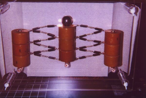
I built my full wave, three stage, Cockcroft-Walton
voltage multiplier from nine 2500 picofarad, 30 kVDC, ceramic capacitors
and twenty-four 12 kVDC, 350 mA, diodes. The unit is mounted on three pieces
of 1/2" square copper bar stock, which are held between two 12" X 18" X
1/2" sheets of polycarbonate. The plastic sheets are held together with
1/4-20 nylon threaded rods, nylon wing nuts, and 2 1/2" lengths of 1" OD,
3/4" ID polycarbonate tube at each corner. The copper bars each have a
1/4-20 tapped hole in the middle, both ends were filed down to 1/2" diameter
and one end was drilled to accept a banana plug. Copper straps and solder
connect the capacitors and diodes together. With 75 VAC in to the transformer,
the voltage at the output terminal was 40,000 VDC (the maximum rating of
my high voltage probe). With 120 volts in, this corresponds to an output
of 64,000 VDC, pretty close to what I calculated above. The grid blocks
in the lower left hand corner of the picture are 1" square. I put a paper
towel over the back of the unit to give the picture better contrast.
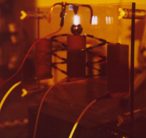
Here it is hooked up to (and sitting on top of)
my 15 kVAC neon sign transformer, with 120 volt input. A point electrode,
made from aluminum roof flashing, is suspended over the top electrode and
grounded via a 23 megaohm current limiting resistor network.
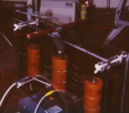
This picture shows a simple electrostatic motor set up and ready to
run. The rotor is made from two pieces of aluminum roof flashing, held
together with aluminum duct tape and sits on a needle point ground from
a piece of 1/8" drill rod. The rod sits in a hole in a piece of 1/2" square
copper bus bar, which is connected to the C-W output terminal with a small
piece of flashing.
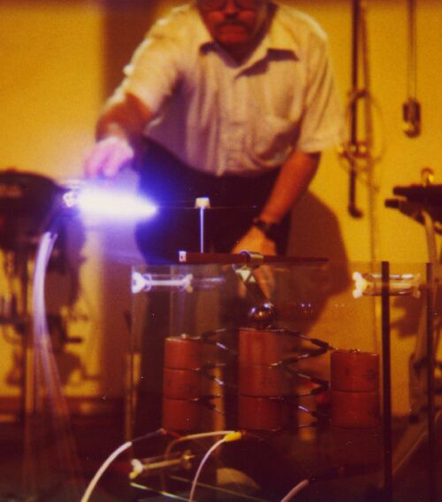
Here I am, drawing a very impressive (and loud) 4" arc from the rim
of the running motor to a grounded (no limiting resistor) steel sphere.
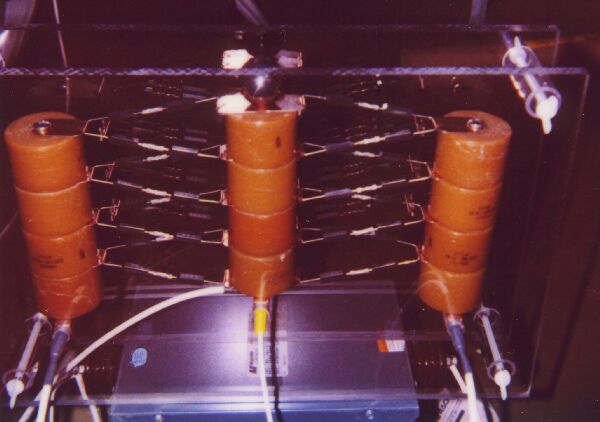
Here is a picture of my new, four stage, full wave Cockcroft-Walton
voltage multiplier (after my can crusher
killed the three stage unit above). Besides having four stages, the new
unit uses crimp style butt connectors to join the diodes together and home
made spring clips to connect the diodes and capacitors instead of solder
(so the next time I blow all of the diodes, I can just plug in new ones).
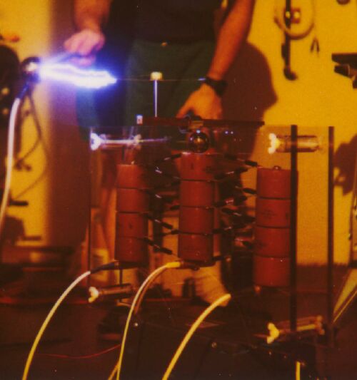
The new CW in action, with ion motor and spark. It puts out 40,000
volts with a 62 volt input (compare to 3 stage, above) and when hooked
up to an old panel style milliamp meter, 8 ma with 120 volts input.